Components of an industrial image processing system
Depending on the application environment, we select the optimal configuration of the right cameras, optics, lighting and image processing systems for you:
Area Scan Camera
Equipped with a 2D camera chip (monochrome or color), can reach frame rates up to over 100 Hz. Mainly used for examination of slow mooving or still objects. Easy to configure and cost-efficient.
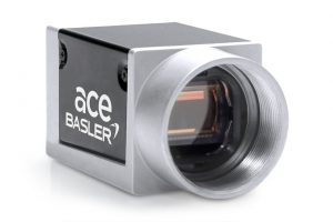
Area scan camera with small formfactor (29×29 mm): Basler ace Serie.
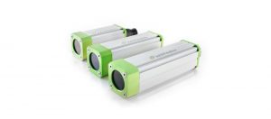
Line Camera
Equipped with a 1D-Kamerachip (monochrome or color) and can reach line frequencies of over 70 kHz. Because of these high framerates especially fitted for usecases, that concern fast moving objects or continuous material. For wide tracks, several Line scan cameras can be used simultaneously to cover the whole area. In most cases the line-capturing process is controlled by a sensor (rotary encoder).

Compact line scan camera: Basler racer series.
Optics
Depending on the task, we use normal, zoom, macro or telecentric lenses. For certain lighting scenarios, these are supplemented by filters (polarization, bandpass). In harsch environments the sensitive optics and camera hardware can be protected by specially adapted housings.
Camera housing with IP67 and accesories like wind curtain, watercooling or heating: AutoVimation Salamander.
Lighting
Depending on the size of the object, material properties and the environment, a variety of different lighting methods are used:
– Diffuse dome lighting for shadow-free illumination of 3D objects.
– Surface luminaires with HF-tubes to light large surfaces.
– Strobe flash lighting for fast mooving subjects.
– Fiber optics for illumination in thight space conditions.
– High-power LED lighting in various geometrics and spectral colors (Suitable even if ambient light is present).
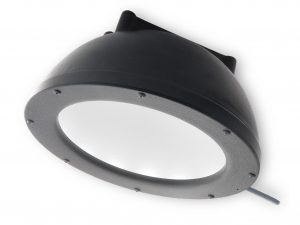
Diffuse dome lighting (indirect „cloudy day illumination“): Advanced Illumination DL 097
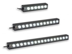
High-Power LED bar light (variable length): Advanced Illumination LL174
Image processing system
In addition to server PC systems and IPCs, “Smart Cameras” (Embedded Systems) are frequently used. The classic smart camera is suitable for individual testing tasks in the industrial environment. For more complex test benches that require the use of more than one camera, an industrial PC or embedded computer with multiple camera interfaces (GigE Vision, USB3 Vision, CameraLink) is used.

Smart Camera series Matrox Iris GTR with IP67 protection and direct interfaces to PLC controls.
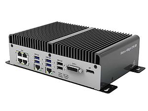
Fanless embedded computer Matrox 4Sight EV6, direct connection of up to 8 industrial cameras.
Control
The seamless connection to PLC controls and process control systems is important for integration in automated industrial systems. Communication with our vision systems can take place via industry and laboratory standards or via customer-specific protocols. Possible interfaces are: digital I / O, serial, Ethernet, Profibus or Profinet standard, OPC or direct database access (SQL Server, Oracle, etc.).